Since 1949 Nippondenso has produced several types and sizes for various types mein starter. Of a small gasoline engine machine to machine tool equipment.
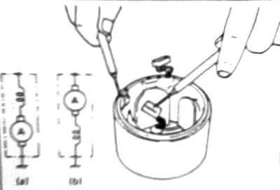
Nippondenso starter can be grouped into two types (corresponding to the connecting pinion mechanism):
Nippondenso starter can be grouped into two types (corresponding to the connecting pinion mechanism):
1.TYPE KONVENSIONAL
TYPE F dan G
2. TYPE REDUKSI
TYPE R
TYPE KONVENSIONAL
Nippondenso starter conventional type are grouped as follows ; fig. 1-1

REDUCTION TYPE
Reduction Nippondenso starter type is classified as follows ; fig. 1-2

STARTER TYPE CONVENTIONAL
overview
Setarter of this type in use on many cars, only the pinion and overrunning clutch is in sliding the lever / drive lever (on the move by solenoid) that drew together degan ring gear.
fig. 3-1 ;

YOKE ASSY
pole core function is to support the field coil and serves to strengthen the field. magnetic field generated by the coil. in general, each motor starter has 4 pieces of pole cores are tied to the yoke core (body starter) with a screw.
fig. 3-2.

ARMATURE ASSY
Armature assy consists of; almature shaft, helical spline, armature winding, and commutator core almature. In general almature serves to transform electrical energy into mechanical energy (rotary motion)

Armature core is in the form of an iron bar that serves as Sylinder slotted iron core of the coil
armature.
Rests on the armature shaft bearing 2 or 3 brush.
Helical splines on the shaft to allow for overrunning. clutch when shifting subtly linked to the ring gear.
Loops / coils located on the armature core and in isolation from one another and it ends at the end of segments connected to comulator.
OVERRUNING CLUTCH ASSY
Allows Overruning pinion clutch spins faster than almature after engine start. Prevent damage due to armature inches fugal force at high speeds.
Overruning clutch consists of;
Driving member who is connecting with a spline tube
driven member which connect to the pinion.
clutch splings
Cylindrical rollers.
fig 3-4.

There are 5 or more between the driven roller and the driving member, rollers are located in holes or cracks. The outer surface of the gap is slightly tilted and tapered (tapered) every rollers are driven toward the tapered part of the gap by a small coil spring.
fig. 3-5.

When auter barrel rotates clockwise toward the roller will compress and unify the outer barrel and inner barrel so that the outer barrel and inner barrel rotates in the same direction. circumstances caused because the roller on the press by the outer spring and round barrel.
fig. 3-6.

If the machine has been living the pinion will rotate faster than the outer barrel. As a result, the roller will move from its original position to allow the outer from the inner barrel rotates freely. Thus the spin rotation due to the ring gear pinion is not forwarded to the armature.
fig. 3-7

.
MAGNETIC SWITCH ASSY
Magnetic switch consists of; selenoid, a magnetic core, plunger. (Core motion). Spring return, contacts and terminals. Selenoid coil is composed of 2; pull in coil (pull) and hold in coil (barrier) which functions to move the pinion so intertwined with the engine ring gear by pulling and holding the plunger.
Fig 3-8.

When the starting switch (SS) is closed (on). when the starting switch on the lid as shown in the image of current flow that occurs is;
fig.3-9.


Magnetic force generated by the pull in and hold in coil will pull the plunger so that the pinion shift lever will drive forward towards the ring gear.
fig 3-30


When the main switch is closed.
At the main switch is closed pull in coil in non-disabled to bypass the C MT. Electric current flowing in a direction of the arrow and rotate the starter to start engine.
At this time hold the plunger in position attracted by the magnetic force of the hold in coil.Saat starting switch off.
At the open da SS MS closed a current flows in the direction pointed by arrows,
fig. 3-11
B------------.> MS ----------->. PC ----------.> HC ----------> E

3-10 compared with the current image is now flowing through the PC and HC in the same direction (kemagnitannya weaken each other) that causes the magnetic force on the HC is reduced, then MS is open and the plunger back to its original position with the help of the return spring.
DRIVE END FRAME
One part of the drive end frame cover overrunning clutch and the drive lever which serves to provide protection from dust and corrosive air. Oilless bush pressed (meeting) on the drive end frame thereby providing a longer service interval.
fig.3-12

.
REAR END FRAME
Also in the pres bush Oilless fit (meeting) on the rear end frame. Grease on add on the back cover to lubricate the brake spring.
fig. 3-13

DRIVE LEVER
When the starting switch in the closed fig 3-14 (B) the plunger would be interested, so that the pinion move forward simultaneously towards the ring gear. In this condition, although the pinion does not go right to the ring gear until the plunger will remain interested in playing contact is closed. Fig.3-14 (C). Sat around a closed contact armature begins to spin. As a result entered the ring gear pinion. So the drive lever and spring produce motion in (convergence) is smooth and efficient
fig 3-14 A

GBR 3-14B

GBR 3-14C

DISASSEMBLY
The following figure shows the component parts of the conventional type starter
fig. 3-15
starter type Konvensional ; Gbr 3-16

Dismantling of motor starter


ARMATURE
Armature short circuit test
Place the armature on a growler tester and hold the saw with the blade facing the armature and the armature rotate slowly, if there is a short-circuit the chain saw to vibrate and be attracted to the armature. Armature connected to short to be replaced or repaired.
fig. .3-29


Examination of the surface of the commutator
Check the surface of the commutator which often leads to open and improve relations with leveling using fine sandpaper # 400 or the like if necessary in view.
fig.3-30


Test run out the commutator
Fig.3-30 check as reimbursement limit;> 04mm. when it reached the limit, fix or replace
Test earthing armature windings By using the tester, connect one probe to the commutator and the other probe to the armature core of this condition should be no relationship.
fig.3-31


Measurement her feet out of the commutator
fig.3-32


Mica segment depth measurements.
Check the depth of the replacement boundary segment mica; <0.2 mm.
Fig.3-33

Estrangement between the bush and the armature shaftFront end and the armature shaft bush
Rear end bush and armature shaft
Limit of measurement; (A - B)> 0.2 mm.
Fig.3-34

Bush replacement.
Replace the bush like a fig. 3-35

Replace with a new bush like Fig.3-36

Note: When changing bush, estrangement between the shaft and the bush around 0.05 mm, and give advice within their grease.
YOKE
By using the tester, connect the probe as Fig.3-37. be related
There are two types of ground (earth)
Armature Earth
Field Earth
gbr.3-37

BRUSH AND BRUSH HOLDER
The length of brush
Reimbursement limit; <2/3 of the length of a new brush.
Fig.3-38


Check Brush Spring
Check Brush Spring of damage or dirty replace if necessary
Check the insulation capability Brush holder
Using a tester, connect one probe to the brush holder plate
Should be no relationship, if the connected switch
Fig.3-39

OVERRUNNING CLUTCH TEST OVERRUNNING
Check if the overrunning clutch spins freely in the direction of rotation starter and locked
In the opposite direction.
Fig.3-40

MAGNETIC SWITCH TEST
To keep in order to avoid the possibility of burning the test of time ranging from 3-5 seconds
To simplify the explanation below at some of the abbreviations mean;
MT ------------- Main Terminal
To penempatkan main cable from the battery, commonly called terminal MT
C -------------- C-terminal placement of Fielding Lead wire coil
50---------- --- 50 - Terminal for the placement of the lead wire from the starting switch.

PULL –IN TEST
Cable connections as shown .3-41. When the flow of electricity from the battery is connected.Pinion should move out.
HOL –IN TEST
With the same conditions on the pull-in test, remove the C-terminal
Pinion will remain in a condition to move out.
Fig.3-42
Pinion will remain in a condition to move out.
Fig.3-42
RETURN TEST
With the same conditions as hold-in test, take off the C-terminal and 50-terminal.
Pinion should kemali to the starting position.
Fig.3-43

Pinion should kemali to the starting position.
Fig.3-43

Re-assembly starter motor
lubrication
Before the raft again, lubricate with suitable lubricant on parts such as the following (black);
Figure 3-44.

Installation of SNAP RING
After installing a new stop collar on the armature shaft.masukkan snap ring into the armature shaft. make sure the snap ring is properly installed.
Knock pinion to insert a stop collar on the upper / outer snap ring.
With pressure, Ensure stop collar by pressing on two or three places.
Figure 3-45.

BRUSH ASSEMBLY
( Type Heavy duty )
fig. 3-46

.
( Type Linght duty ) assembly negative brush tobrush holder and brush positif to brush holder positif. make sure the positive wire brush the conductor does not touch ground / starter body.
Fig 3-47
Fig 3-47

.
3-48.

DRIVE LEVER
Replace the drive lever as shown in Figure .3-49.


Performance test
The following tests should be done after set up (put) back to the starter motor. if the equipment is in need is not available. doing enough in the no-load test. (No-load-test)No load test
Pinch starter with a vise and use a good battery and ammeter. Connect the starter as a series of 3-50 fig. Starter will move smoother and faster spinning immediately after the pinion spring forth and ammeter shows the current price is less than specified.
Fig 3-50

Load test
Read the value of the ampere meter and volt meter while the starter in the given load. ampere meter always showed values below the current value specified.Fig 3-51

Read the torque meter and tachometer ampere meter while the price (0) rpm, after the load. Torque meter should show the value in the specification and the ammeter is less than the current specification.
Fig 3-52

Heavy duty starter circuit diagram when starting switch is closed the flow of current is as follows;

A large current does not flow into the field coil is not closed because the main terminal. Winding shunt in parallel with the armature winding slowly round the field so that (the current flowing to the small armature). So that when the starter switch is closed and round jump starter plunger slowly. Starter does not have a heavy duty type drive lever spring. Pinion will rotate after the machine was really getting into the ring gear
.
Relay StarterStarter relay to protect the starter switch. because the magnetic switch is larger than the conventional type that requires a large current to operate

.